(update) I have got this working, exactly as described in the Igoe post – The code is in EthernetPachubeTweeter_tz1.
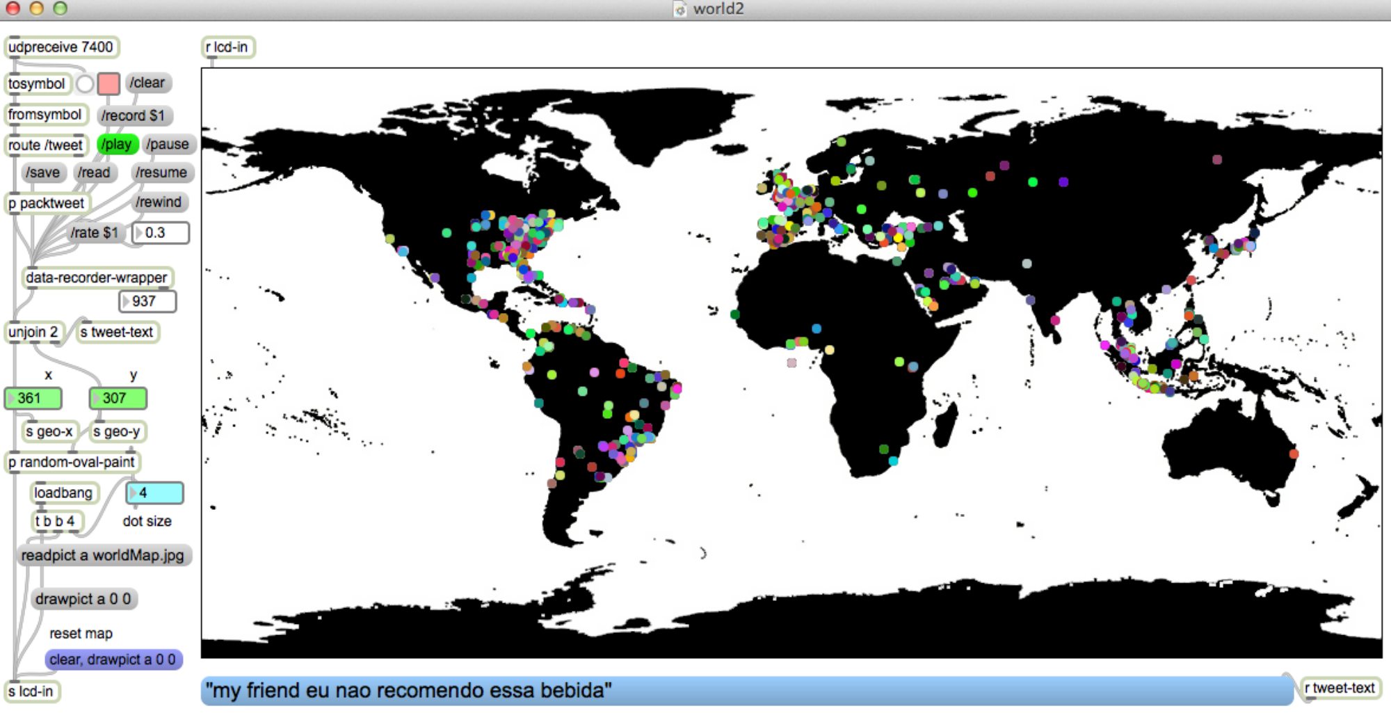
Essentially, anything that originates from the Arduino is sent to a feed in Pachube. That feed has a datastream which has a trigger which tweets any new data which arrives.
The next thing to try is figuring out whether this can be done as a single line http: request in curl, and therefore, from Max – or any other source
The potentiometer on the control radio changes the motor speed of the RC car. A potentiometer on the other side controls the brightness of an LED at the controller.
The xbee radios should be set up as directed – starting on p. 195
Here are the xbee settings:
ATMY
ATDL
ATDH
ATID
Radio 1
1234
5678
0
1111
Radio 2
5678
1234
0
1111
construction
2 stacks:
1) arduino + wireless SD shield + xbee
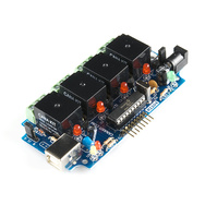
2) arduino + motor shield + wireless SD shield + xbee (motor shield hooked to RC car motor)
Each stack has a potentiometer, tx/rx leds, LED for remote brightness control, and batteries.
The motor shield has connections to the RC car motor and 9V battery for power.
code
Code for radio 1: xbee_full_duplex2_radio1.ino
The motor side uses a few lines of code from an instructables.com motor shield tutorial. LED brightness is linked to motor speed – sent out on pin 3 – from the Arduino sketch:
code for radio 2 (car): xbee_full_duplex2_radio2_motor.ino
note:
When loading the sketch, set the slide switch on the Wireless-SD shield to ‘USB’ – then switch it back to “micro” to run.
If the controller radio (radio 1) is connected to a computer, open the Arduino serial monitor – or the sketch will block – and nothing will happen.
Download
[wpdm_file id=20]
circuit layout
radio 1
pin A0 : input sensor (potentiometer)
pin 2 : tx LED
pin 3 : rx LED
pin 9: test LED (receives brightness data)
radio 2
pin A0 : input sensor (potentiometer)
pin 3: used internally for motor speed – (the motor is hooked to Channel A on the motor shield)
pin 4 : tx LED
pin 5 : rx LED
pin 10: test LED (receives brightness data)
Re-assign some of the pins from the xbee example so they aren’t on the same ones as the motor shield is using: Here’s the pin layout that the motor shield uses. i.e.. these are the pins that are used in an Arduino sketch to control each motor function. This project only controls ‘speed’ on channel A (pin 3).
Function
Channel A
Channel B
Direction
Digital 12
Digital 13
Speed (PWM)
Digital 3
Digital 11
Brake
Digital 9
Digital 8
Current Sensing
Analog 0
Analog 1
notes
This Arduino forum post was also helpful – otherwise I would have assumed that the shields were incompatible: