FM audio transmitter using NTX2

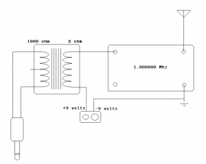
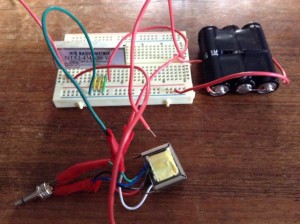
Transmit FM audio on 434.65 Mhz. by substituting a Radiometrix NTX2  for a crystal oscillator in this circuit:

http://scitoys.com/scitoys/scitoys/radio/am_transmitter.html

Radiometrix: http://www.radiometrix.com/content/ntx2

NTX2 datasheet: http://www.radiometrix.com/files/additional/ntx2nrx2.pdf

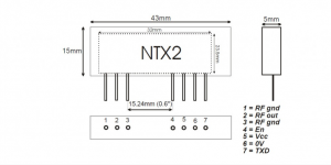
On the NTX2, the connections are:

  • 5V to the NTX2 VCC pin 4
  • 5V to the NTX2 EN pin 5
  • GND to the NTX2 GND pin 6
  • Upper lead of audio transformer to the NTX2 TXD pin 7

A voltage divider input coupler will also work. See this post for a simple circuit: https://reactivemusic.net/?p=12263

notes

  • Audio modulation level is very low. This circuit would benefit from a preamp. For example, as in this circuit by Amanda Ghassaei: http://www.instructables.com/id/Arduino-Audio-Input/
  • Connect an antenna wire to NTX2 pin 2 (and 1 for RF ground)
  • The circuit worked with 3.3 volts and would probably be fine with less.
  • Used line out of an iPod touch for an audio source. Volume was up fairly high.
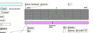
  • You can also receive using AM mode using ‘edge’ detection
  • In the US, you need a ham license to transmit on 434.65 Mhz.

RTTY with Arduino and NTX2

A circuit from the UK High Altitude Balloon sight, that sends RTTY, from Arduino using the Radiometrix NTX2 transmitter on 434.650 Mhz.

http://ukhas.org.uk/guides:linkingarduinotontx2#where_to_buy_the_ntx2

circuit notes

substituted  2 100k resistors in parallel for the 47k connected to TX output in the circuit

RTTY settings

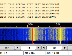
We used rtl-sdr with Max as the receiver, in SSB mode, sending audio via Soundcloud to dl-fldigi to decode the RTTY. The params that worked:

  • 50 baud
  • carrier shift 400-480 hz (varies)
  • 7 bits per char
  • no parity
  • 2 stop bits
  • reverse mode on
audio input monitor in dl-fldigi

Unfortunately there was no way to hear the signal while decoding because dl-fldigi doesn’t feed through the input audio. A workaround is to run  Audacity in the background. In audacity:

  • set input to soundflower,
  • set output to built-in output
  •  press pause
  •  press record – now you should hear the radio.

pwm circuit

An updated version of the system described above.

This circuit features no additional components. Just the NTX2 and Arduino. The voltages are generated using PWM (pulse width modulation).

Described in a 3 part series.

by Anthony Stirk at ava.upuaut.net

http://ava.upuaut.net/?p=617

Example 1 – testing

The first example generates a carrier shift of 310 Hz. It took several minutes for the transmit frequency to stop drifting. The AFC setting in dl-fldigi helps to keep things locked in – as long as their is a constant carrier.

Example 2 – RTTY

Reducing the filter bandwidth to less than 150 Hz helps, due to the narrow carrier shift.

Example 3 – dominoEX MFSK

Requires a 175 ohm resistor for precise timing. Didn’t have one, so I just ran the sketch without decoding. Here’s what it sounds like:

what’s next?
  • decoding RTTY in Max


Stock market music in Max

Make music from the motion of stock prices.

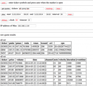
This program gathers stock prices into a database. It generates Midi data – mapping price to pitch, and mapping trading volume to velocity and rhythmic density. It uses ancient Web technology: HTML/javascript front-end with a php back-end accessing a mysql database.

Case study: http://zproject.wikispaces.com/stock+market+music

To run this project, you will need a server (preferably linux) with the following capabilities:

  • mysql + phpmyadmin
  • php (and ability to run php over the web)
  • netcat (nc)
  • network access

All of this is pretty standard – so I won’t talk about it here. I am running it on Ubuntu Linux. There are many other ways to get the project working, by using the layout described here.

download

https://github.com/tkzic/internet-sensors

folder: stock-market

files

Max

stock_market_music.maxpat

HTML/javascript web client
  • newstock3.html: (web page interface)
  • selectstock3.js:  (front-end)
php server
  • getstock3.php (back-end server to get quotes and save them to a database)
  • play3.php: (back-end server to retrieve quotes, analyze, and map to Midi sequence to send to Max)
  • udp.php: Osc library
Set execute privileges on php files so they can be run from your web server. (chmod +x)


database

The selectstock3.php program harvests stock quote data and stores it in a mysql database.

The database name is:  stocks – table is: quotes

Table structure:

The table is basic flat representation of a stock quote, indexed by the ticker symbol. It contains price, volume, high/low/change, timestamp, etc., For our purposes, the price, volume and timestamp are essentially all we need.

SQL to create the table:

 CREATE  TABLE  `stocks`.`quotes` (  `ticker` varchar( 12  )  NOT  NULL ,
 `price` decimal( 10, 2  )  NOT  NULL ,
 `qtime` datetime NOT  NULL ,
 `pchange` decimal( 10, 2  )  NOT  NULL ,
 `popen` decimal( 10, 2  )  NOT  NULL ,
 `phigh` decimal( 10, 2  )  NOT  NULL ,
 `plow` decimal( 10, 2  )  NOT  NULL ,
 `volume` int( 11  )  NOT  NULL ,
 `ttime` timestamp NOT  NULL  DEFAULT CURRENT_TIMESTAMP ,
 `id` int( 11  )  NOT  NULL  AUTO_INCREMENT ,
 `spare` varchar( 30  )  DEFAULT NULL ,
 UNIQUE  KEY  `id` (  `id`  ) ,
 KEY  `ticker` (  `ticker`  )  ) ENGINE  =  MyISAM  DEFAULT CHARSET  = latin1 COMMENT  =  'stock quote transactions';

creating the database, user, and table

  • Log into  phpmyadmin as root
  • Create a new database called ‘stocks’
  • In privileges, add a user called: ‘webdb1′ with a password of ’34door’ (note you can change the password later)
  • In SQL, copy in the above query to create the ‘stocks’ table

Instructions

Web client

The webpage control program allows you to select stocks by ticker symbol, and get either one quote or get quotes at regular time interval. Each quote is inserted into the stock table for later retrieval and analysis.


The web front end is quirky so I will describe it in terms of how you might typically use it:

market is open – and you just want to play music based on current stock prices
  1. Enter the ticker symbols for your stocks
  2. Press ‘tracking’ button – so the quotes get saved
  3. Enter the IP address of the computer running Max
  4. Press the ‘auto’ button in the upper left corner – it will run and play forever
market is closed – or you want to play historical data you have saved
  1. Enter the ticker symbols for your stocks
  2. Enter the IP address of the computer running Max
  3. set start end end dates
  4. Press the ‘play’ button to play once or press ‘loop’ to play continuously (using time interval in seconds)
  5. market is open – you just want to collect stock quote data
  6. Enter the ticker symbols for your stocks
  7. Press the tracking button so quotes will get saved
  8. Press the ‘get quotes’ button to get current quote or press ‘loop’ button (on the same line) to retrieve quotes  continuously every 30 seconds.

Instructions

Max patch

  1. Make sure the IP address is set to the address of your server
  2. Select the Midi port for output
  3. Play a few test notes
  4. Select either ‘one instrument’ mode (piano) or multi instrument mode. Each time you click the multi instrument button it randomly selects a new combination 

notes on stock market data

To look at historical trends, you would need access to historical stock data. To use it as a tool for short term analysis, you would need access to real-time quote data in an API. At the time, both of these cost money.

However, it doesn’t cost money to get recent quotes from Yahoo throughout the day and store them in a database – so that’s the approach I took.

If I were to do this project today, I’d look for a free online source of historical data, in machine-readable form – because the historical data provides the most interesting and organic sounds when converted into music. The instant high speeding trading data would probably make interesting sounds as well, but you still need to pay for the data.

notes on local files

xively.com feed with Arduino

[Note: xively.com is gone. This system doesn’t work. Post is here for historical reasons only]

Bi-directional communication from Arduino to a xively.com feed using an ethernet shield.
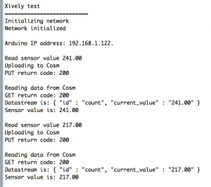
  • Initializes an internet connection (DHCP)
  • Connects to xively.com servers every minute
  • Stores random value in the feed using HTTP PUT
  • Retrieves current feed value using HTTP GET
  • Lights up LED when transmitting
By the way, xively used to be cosm used to be pachube… 
Arduino circuit
  • Use an ethernet shield.
  • Connect ethernet cable. (I am using a Netgear WNCE2001 ethernet to wiFi adapter)
  • LED is connected to pin 5 and ground. The shorter lead connects to ground.

download

[wpdm_file id=18 title=”true” ]

files
  • xively_test1 (Arduino sketch)
Arduino files and libraries

Copy the xively_test1/ folder to Documents/Arduino. This puts it in the Arduino sketchbook.

Notes on installing xively/cosm/pachube libraries for arduino: https://reactivemusic.net/?p=4900

Instructions

  1. Connect Arduino to Macbook via USB.
  2. Open the Arduino serial monitor to initialize the ethernet connection and display the IP address.
  3. Every minute data gets send to the feed
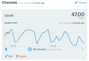
  4. Monitor feed data here: https://xively.com/feeds/98281/workbench
Arduino sketch


/*
5/20/2014 - Arduino/xively feed interaction
Uses Ethernet Shield and and LED connected between pin D5 and ground
Sends a random value to a xively.com feed every minute
The LED lights up during data transmissions
demonstrates:
HTTP PUT - send data to xiveyly feed and store
HTTP GET - read xively feed value
*/
#include <SPI.h>
#include <Ethernet.h>
#include <HttpClient.h>
#include <Cosm.h>
int ledPin = 5;
int upCount = 0; // counters for number of times going up and down
#define API_KEY "96PqSh4rj7HzNif3WtTpN7GjX96SAKxrWms3SUhwaDFGUT0g" // your Cosm API key
#define FEED_ID 98281 // your Cosm feed ID
// MAC address for your Ethernet shield
byte mac[] = { 0x90, 0xA2, 0xDA, 0x0D, 0x0B, 0xCE };
// note that pins 0 and 1 are used by the Ethernet shield
unsigned long lastConnectionTime = 0; // last time we connected to Cosm
const unsigned long connectionInterval = 60000; // delay between connecting to Cosm in milliseconds
// Initialize the Cosm library
// Define the string for our datastream ID
char sensorId[] = "count";
CosmDatastream datastreams[] = {
 CosmDatastream(sensorId, strlen(sensorId), DATASTREAM_FLOAT),
};
// Wrap the datastream into a feed
CosmFeed feed(FEED_ID, datastreams, 1 /* number of datastreams */);
EthernetClient client;
CosmClient cosmclient(client);
void setup() {

 // initialize the detector pins 

 pinMode(ledPin, OUTPUT ); // internet transmitting indicator
 // start the Monitor (console) serial port

 Serial.begin(9600);
// display happy messages 

 Serial.println("Xively test");
 Serial.println("==========================");
// Keep trying to initialize the Internet connection
 // Note - we should eventually timeout of this and just run the stairs independently

 Serial.println("Initializing network");
 while (Ethernet.begin(mac) != 1) {
 Serial.println("Error getting IP address via DHCP, trying again...");
 delay(15000);
 }
Serial.println("Network initialized");
 Serial.println();
 // print your local IP address:
 Serial.print("Arduino IP address: ");
 for (byte thisByte = 0; thisByte < 4; thisByte++) {
 // print the value of each byte of the IP address:
 Serial.print(Ethernet.localIP()[thisByte], DEC);
 Serial.print("."); 
 }
 Serial.println();
 Serial.println();

} // end of setup function
//////////////////////////// control loop ///////////////////////////
void loop() {
 // main program loop

 ////////////////////////////// Internet sending/receiving code ////////////////////////////////

 if (millis() - lastConnectionTime > connectionInterval) {

 // uncomment this to just send a random value...
 upCount = random(256);

 digitalWrite(ledPin, HIGH ); // turn on transmitter light
 sendData(upCount);
 // read the datastream back from Cosm - comment out to save time
 getData();
 digitalWrite(ledPin, LOW );
 // update connection time so we wait before connecting again
 lastConnectionTime = millis();

 }

 ///////////////////// end of internet send/receive code /////////////////

} // end of main loop code
/////////////////// additional functions //////////////////////////
////////////////////////////////////////////////////////////////////
// send the supplied value to Cosm, printing some debug information as we go
void sendData(int sensorValue) {
 datastreams[0].setFloat(sensorValue);
Serial.print("Read sensor value ");
 Serial.println(datastreams[0].getFloat());
Serial.println("Uploading to Cosm");
 int ret = cosmclient.put(feed, API_KEY);
 Serial.print("PUT return code: ");
 Serial.println(ret);
Serial.println();
}
// get the value of the datastream from Cosm, printing out the value we received
void getData() {
 Serial.println("Reading data from Cosm");
int ret = cosmclient.get(feed, API_KEY);
 Serial.print("GET return code: ");
 Serial.println(ret);
if (ret > 0) {
 Serial.print("Datastream is: ");
 Serial.println(feed[0]);
Serial.print("Sensor value is: ");
 Serial.println(feed[0].getFloat());
 }
Serial.println();
}
 

basic Arduino connections to Max

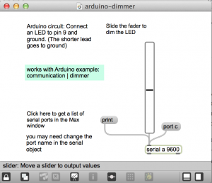
  • Dim an LED from Max.
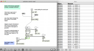
  • Read the value of a potentiometer in Max.

download

https://github.com/tkzic/max-projects

folder: arduino-basics

patches:

  • arduino-dimmer.maxpat
  • arduino-serial-read.maxpat

Arduino dimmer

dim an LED from Max

From the Arduino playground

http://playground.arduino.cc//Code/MaxCommunicationExamples

circuit

Connect an LED to pin 9 and ground. The shorter lead goes to ground.

sketch

Load the Arduino example sketch: communications | dimmer

Max
  1. open arduino-dimmer.maxat
  2. Click the “print” message to print the list of ports to the Max window. Then set the port in the serial object, using the port message. For example: “port c”.
  3. Move the slider to dim the LED

Arduino serial read

Read the value of a potentiometer

This patch is a bit more involved. Refer to the Max Communications Tutorial 2: Serial Communication. In fact, much of this code was lifted from the tutorial.

circuit
  • Connect an LED to pin 9 and ground. The shorter lead goes to ground.
  • Connect a potentiometer (center lead) to Analog pin 0. The side leads connect to +5v and ground.
sketch

Load the Arduino example sketch: Analog | analogInOutSerial

Max
  1. Open arduino-serial-read.maxpat
  2. Click the “print” message to print the list of ports to the Max window. Then set the port in the serial object, using the port message. For example: “port c”.
  3. Activate toggle to start polling serial port
  4. Activate toggle number 3 to view formatted output in the Max window
  5. Turn the potentiometer to send data to Max

general suggestions:

  • Try not to get discouraged.
  • If weird things happen, close Max, reconnect Arduino, the re-open Max