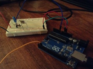
Transmit AM audio on 727 KHz. using a voltage divider and an Arduino.
By Markus Gritsch
Note: with the actual circuit the signal is closer to 760 KHz.
Samples incoming audio at 34 KHz. and rebroadcasts as RF using the Arduino clock.
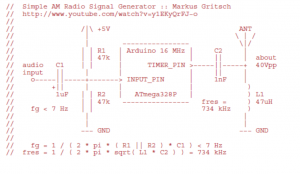
This is a simplification of Markus’ original circuit. It eliminates the tuned output circuit. Probably at the expense of increased harmonic distortion.
The voltage divider is uses 2 47K Ohm resistors and a 1 uF electrolytic capacitor. It is the input half of the original circuit.
http://dangerousprototypes.com/forum/viewtopic.php?f=56&t=2892#p28410
(I substituted 2 100 K Ohm resistors in parallel for each of the 47 K’s.)
A voltage divider is useful as a general purpose coupler, for sampling analog signals using Arduino PWM input.
The Arduino sketch is Markus’ original – reprinted here:
(note) Local file is AM_audio_transmitter.
// Simple AM Radio Signal Generator :: Markus Gritsch
// http://www.youtube.com/watch?v=y1EKyQrFJ−o
//
// /|\ +5V ANT
// | \ | /
// | −−−−−−−−−−−−−−−− \|/
// | | R1 | Arduino 16 MHz | C2 |
// | | 47k | | || | about
// audio C1 | | | TIMER_PIN >−−−−−||−−−−−+ 40Vpp
 // input || | | | || |
 // o−−−−−||−−−−−+−−−−−−−> INPUT_PIN | 1nF |
 // +|| | | | )
 // 1uF | | R2 | ATmega328P | ) L1
 // | | 47k −−−−−−−−−−−−−−−− fres = ) 47uH
 // fg < 7 Hz | | 734 kHz )
 // | |
 // | |
 // −−− GND −−− GND
 //
 // fg = 1 / ( 2 * pi * ( R1 || R2 ) * C1 ) < 7 Hz
 // fres = 1 / ( 2 * pi * sqrt( L1 * C2 ) ) = 734 kHz

#define INPUT_PIN 0 // ADC input pin
#define TIMER_PIN 3 // PWM output pin, OC2B (PD3)
#define DEBUG_PIN 2 // to measure the sampling frequency
#define LED_PIN 13 // displays input overdrive

#define SHIFT_BY 3 // 2 ... 7 input attenuator
#define TIMER_TOP 20 // determines the carrier frequency
#define A_MAX TIMER_TOP / 4

void setup() {
pinMode( DEBUG_PIN, OUTPUT );
pinMode( TIMER_PIN, OUTPUT );
pinMode( LED_PIN, OUTPUT );

// set ADC prescaler to 16 to decrease conversion time (0b100)
ADCSRA = ( ADCSRA | _BV( ADPS2 ) ) & ~( _BV( ADPS1 ) | _BV( ADPS0 ) );

// non−inverting; fast PWM with TOP; no prescaling
TCCR2A = 0b10100011; // COM2A1 COM2A0 COM2B1 COM2B0 − − WGM21 WGM20
TCCR2B = 0b00001001; // FOC2A FOC2B − − WGM22 CS22 CS21 CS20

// 16E6 / ( OCR2A + 1 ) = 762 kHz @ TIMER_TOP = 20
OCR2A = TIMER_TOP; // = 727 kHz @ TIMER_TOP = 21
OCR2B = TIMER_TOP / 2; // maximum carrier amplitude at 50% duty cycle
}

void loop() {
// about 34 kHz sampling frequency
digitalWrite( DEBUG_PIN, HIGH );
int8_t value = (analogRead( INPUT_PIN ) >> SHIFT_BY ) - (1 << (9 - SHIFT_BY ));

digitalWrite( DEBUG_PIN, LOW );

// clipping

if( value < -A_MAX) {

  value = -A_MAX;
  digitalWrite( LED_PIN, HIGH );
  } else if ( value > A_MAX ) {
  value = A_MAX;
  digitalWrite( LED_PIN, HIGH );
  } else {
  digitalWrite( LED_PIN, LOW );
  }

OCR2B = A_MAX + value;

}


