AM audio transmitter using Arduino

Transmit AM audio on 727 KHz. using a voltage divider and an Arduino.

By Markus Gritsch

Note: with the actual circuit the signal is closer to 760 KHz.

Samples incoming audio at 34 KHz. and rebroadcasts as RF using the Arduino clock.

This is a simplification of Markus’ original circuit. It eliminates the tuned output circuit. Probably at the expense of increased harmonic distortion.
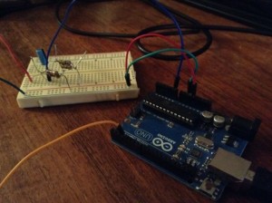
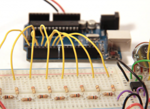
The voltage divider is uses 2 47K Ohm resistors and a 1 uF electrolytic capacitor. It is the input half of the original circuit.

http://dangerousprototypes.com/forum/viewtopic.php?f=56&t=2892#p28410
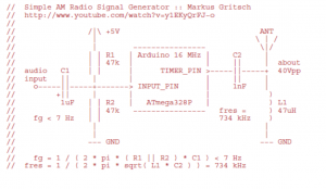
(I substituted 2 100 K Ohm resistors in parallel for each of the 47 K’s.)

A voltage divider is useful as a general purpose coupler, for sampling analog signals using  Arduino PWM input.

The Arduino sketch is Markus’ original – reprinted here:

(note) Local file is AM_audio_transmitter.

// Simple AM Radio Signal Generator :: Markus Gritsch
// http://www.youtube.com/watch?v=y1EKyQrFJ−o
//
// /|\ +5V ANT
// | \ | /
// | −−−−−−−−−−−−−−−− \|/
// | | R1 | Arduino 16 MHz | C2 |
// | | 47k | | || | about
// audio C1 | | | TIMER_PIN >−−−−−||−−−−−+ 40Vpp
 // input || | | | || |
 // o−−−−−||−−−−−+−−−−−−−> INPUT_PIN | 1nF |
 // +|| | | | )
 // 1uF | | R2 | ATmega328P | ) L1
 // | | 47k −−−−−−−−−−−−−−−− fres = ) 47uH
 // fg < 7 Hz | | 734 kHz )
 // | |
 // | |
 // −−− GND −−− GND
 //
 // fg = 1 / ( 2 * pi * ( R1 || R2 ) * C1 ) < 7 Hz
 // fres = 1 / ( 2 * pi * sqrt( L1 * C2 ) ) = 734 kHz

#define INPUT_PIN 0 // ADC input pin
#define TIMER_PIN 3 // PWM output pin, OC2B (PD3)
#define DEBUG_PIN 2 // to measure the sampling frequency
#define LED_PIN 13 // displays input overdrive

#define SHIFT_BY 3 // 2 ... 7 input attenuator
#define TIMER_TOP 20 // determines the carrier frequency
#define A_MAX TIMER_TOP / 4

void setup() {
pinMode( DEBUG_PIN, OUTPUT );
pinMode( TIMER_PIN, OUTPUT );
pinMode( LED_PIN, OUTPUT );

// set ADC prescaler to 16 to decrease conversion time (0b100)
ADCSRA = ( ADCSRA | _BV( ADPS2 ) ) & ~( _BV( ADPS1 ) | _BV( ADPS0 ) );

// non−inverting; fast PWM with TOP; no prescaling
TCCR2A = 0b10100011; // COM2A1 COM2A0 COM2B1 COM2B0 − − WGM21 WGM20
TCCR2B = 0b00001001; // FOC2A FOC2B − − WGM22 CS22 CS21 CS20

// 16E6 / ( OCR2A + 1 ) = 762 kHz @ TIMER_TOP = 20
OCR2A = TIMER_TOP; // = 727 kHz @ TIMER_TOP = 21
OCR2B = TIMER_TOP / 2; // maximum carrier amplitude at 50% duty cycle
}

void loop() {
// about 34 kHz sampling frequency
digitalWrite( DEBUG_PIN, HIGH );
int8_t value = (analogRead( INPUT_PIN ) >> SHIFT_BY ) - (1 << (9 - SHIFT_BY ));

digitalWrite( DEBUG_PIN, LOW );

// clipping

if( value < -A_MAX) {

  value = -A_MAX;
  digitalWrite( LED_PIN, HIGH );
  } else if ( value > A_MAX ) {
  value = A_MAX;
  digitalWrite( LED_PIN, HIGH );
  } else {
  digitalWrite( LED_PIN, LOW );
  }

OCR2B = A_MAX + value;

}


FM audio transmitter using NTX2

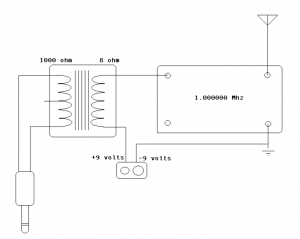
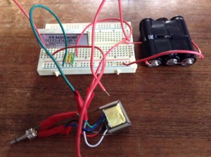
Transmit FM audio on 434.65 Mhz. by substituting a Radiometrix NTX2  for a crystal oscillator in this circuit:

http://scitoys.com/scitoys/scitoys/radio/am_transmitter.html

Radiometrix: http://www.radiometrix.com/content/ntx2

NTX2 datasheet: http://www.radiometrix.com/files/additional/ntx2nrx2.pdf

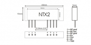
On the NTX2, the connections are:

  • 5V to the NTX2 VCC pin 4
  • 5V to the NTX2 EN pin 5
  • GND to the NTX2 GND pin 6
  • Upper lead of audio transformer to the NTX2 TXD pin 7

A voltage divider input coupler will also work. See this post for a simple circuit: https://reactivemusic.net/?p=12263

notes

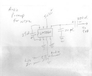
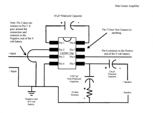
  • Audio modulation level is very low. This circuit would benefit from a preamp. For example, as in this circuit by Amanda Ghassaei: http://www.instructables.com/id/Arduino-Audio-Input/
  • Connect an antenna wire to NTX2 pin 2 (and 1 for RF ground)
  • The circuit worked with 3.3 volts and would probably be fine with less.
  • Used line out of an iPod touch for an audio source. Volume was up fairly high.
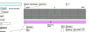
  • You can also receive using AM mode using ‘edge’ detection
  • In the US, you need a ham license to transmit on 434.65 Mhz.

RTTY with Arduino and NTX2

A circuit from the UK High Altitude Balloon sight, that sends RTTY, from Arduino using the Radiometrix NTX2 transmitter on 434.650 Mhz.

http://ukhas.org.uk/guides:linkingarduinotontx2#where_to_buy_the_ntx2

circuit notes

substituted  2 100k resistors in parallel for the 47k connected to TX output in the circuit

RTTY settings

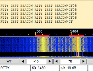
We used rtl-sdr with Max as the receiver, in SSB mode, sending audio via Soundcloud to dl-fldigi to decode the RTTY. The params that worked:

  • 50 baud
  • carrier shift 400-480 hz (varies)
  • 7 bits per char
  • no parity
  • 2 stop bits
  • reverse mode on
audio input monitor in dl-fldigi

Unfortunately there was no way to hear the signal while decoding because dl-fldigi doesn’t feed through the input audio. A workaround is to run  Audacity in the background. In audacity:

  • set input to soundflower,
  • set output to built-in output
  •  press pause
  •  press record – now you should hear the radio.

pwm circuit

An updated version of the system described above.

This circuit features no additional components. Just the NTX2 and Arduino. The voltages are generated using PWM (pulse width modulation).

Described in a 3 part series.

by Anthony Stirk at ava.upuaut.net

http://ava.upuaut.net/?p=617

Example 1 – testing

The first example generates a carrier shift of 310 Hz. It took several minutes for the transmit frequency to stop drifting. The AFC setting in dl-fldigi helps to keep things locked in – as long as their is a constant carrier.

Example 2 – RTTY

Reducing the filter bandwidth to less than 150 Hz helps, due to the narrow carrier shift.

Example 3 – dominoEX MFSK

Requires a 175 ohm resistor for precise timing. Didn’t have one, so I just ran the sketch without decoding. Here’s what it sounds like:

what’s next?
  • decoding RTTY in Max