[Note: xively.com is gone. This system doesn’t work. Post is here for historical reasons only]
Bi-directional communication from Arduino to a xively.com feed using an ethernet shield.

- Initializes an internet connection (DHCP)
- Connects to xively.com servers every minute
- Stores random value in the feed using HTTP PUT
- Retrieves current feed value using HTTP GET
- Lights up LED when transmitting
By the way, xively used to be cosm used to be pachube…
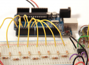
Arduino circuit
- Use an ethernet shield.
- Connect ethernet cable. (I am using a Netgear WNCE2001 ethernet to wiFi adapter)
- LED is connected to pin 5 and ground. The shorter lead connects to ground.
download
[wpdm_file id=18 title=”true” ]
files
- xively_test1 (Arduino sketch)
Arduino files and libraries
Copy the xively_test1/ folder to Documents/Arduino. This puts it in the Arduino sketchbook.
Notes on installing xively/cosm/pachube libraries for arduino: https://reactivemusic.net/?p=4900
- Connect Arduino to Macbook via USB.
- Open the Arduino serial monitor to initialize the ethernet connection and display the IP address.
- Every minute data gets send to the feed
- Monitor feed data here: https://xively.com/feeds/98281/workbench
Arduino sketch
/*
5/20/2014 - Arduino/xively feed interaction
Uses Ethernet Shield and and LED connected between pin D5 and ground
Sends a random value to a xively.com feed every minute
The LED lights up during data transmissions
demonstrates:
HTTP PUT - send data to xiveyly feed and store
HTTP GET - read xively feed value
*/
#include <SPI.h>
#include <Ethernet.h>
#include <HttpClient.h>
#include <Cosm.h>
int ledPin = 5;
int upCount = 0; // counters for number of times going up and down
#define API_KEY "96PqSh4rj7HzNif3WtTpN7GjX96SAKxrWms3SUhwaDFGUT0g" // your Cosm API key
#define FEED_ID 98281 // your Cosm feed ID
// MAC address for your Ethernet shield
byte mac[] = { 0x90, 0xA2, 0xDA, 0x0D, 0x0B, 0xCE };
// note that pins 0 and 1 are used by the Ethernet shield
unsigned long lastConnectionTime = 0; // last time we connected to Cosm
const unsigned long connectionInterval = 60000; // delay between connecting to Cosm in milliseconds
// Initialize the Cosm library
// Define the string for our datastream ID
char sensorId[] = "count";
CosmDatastream datastreams[] = {
 CosmDatastream(sensorId, strlen(sensorId), DATASTREAM_FLOAT),
};
// Wrap the datastream into a feed
CosmFeed feed(FEED_ID, datastreams, 1 /* number of datastreams */);
EthernetClient client;
CosmClient cosmclient(client);
void setup() {

 // initialize the detector pins

 pinMode(ledPin, OUTPUT ); // internet transmitting indicator
 // start the Monitor (console) serial port

 Serial.begin(9600);
// display happy messages

 Serial.println("Xively test");
 Serial.println("==========================");
// Keep trying to initialize the Internet connection
 // Note - we should eventually timeout of this and just run the stairs independently

 Serial.println("Initializing network");
 while (Ethernet.begin(mac) != 1) {
 Serial.println("Error getting IP address via DHCP, trying again...");
 delay(15000);
 }
Serial.println("Network initialized");
 Serial.println();
 // print your local IP address:
 Serial.print("Arduino IP address: ");
 for (byte thisByte = 0; thisByte < 4; thisByte++) {
 // print the value of each byte of the IP address:
 Serial.print(Ethernet.localIP()[thisByte], DEC);
 Serial.print(".");
 }
 Serial.println();
 Serial.println();

} // end of setup function
//////////////////////////// control loop ///////////////////////////
void loop() {
 // main program loop

 ////////////////////////////// Internet sending/receiving code ////////////////////////////////

 if (millis() - lastConnectionTime > connectionInterval) {

 // uncomment this to just send a random value...
 upCount = random(256);

 digitalWrite(ledPin, HIGH ); // turn on transmitter light
 sendData(upCount);
 // read the datastream back from Cosm - comment out to save time
 getData();
 digitalWrite(ledPin, LOW );
 // update connection time so we wait before connecting again
 lastConnectionTime = millis();

 }

 ///////////////////// end of internet send/receive code /////////////////

} // end of main loop code
/////////////////// additional functions //////////////////////////
////////////////////////////////////////////////////////////////////
// send the supplied value to Cosm, printing some debug information as we go
void sendData(int sensorValue) {
 datastreams[0].setFloat(sensorValue);
Serial.print("Read sensor value ");
 Serial.println(datastreams[0].getFloat());
Serial.println("Uploading to Cosm");
 int ret = cosmclient.put(feed, API_KEY);
 Serial.print("PUT return code: ");
 Serial.println(ret);
Serial.println();
}
// get the value of the datastream from Cosm, printing out the value we received
void getData() {
 Serial.println("Reading data from Cosm");
int ret = cosmclient.get(feed, API_KEY);
 Serial.print("GET return code: ");
 Serial.println(ret);
if (ret > 0) {
 Serial.print("Datastream is: ");
 Serial.println(feed[0]);
Serial.print("Sensor value is: ");
 Serial.println(feed[0].getFloat());
 }
Serial.println();
}