From a Max/MSP tutorial: http://cycling74.com/docs/max5/tutorials/msp-tut/mspchapter04.html at Cycling 74
Changing the phase of a waveform
For the most part, the phase offset of an isolated audio wave doesn’t have a substantial effect perceptually. For example, a sine wave in the audio range sounds exactly like a cosine wave, even though there is a theoretical phase difference of a quarter cycle. For that reason, we have not been concerned with the rightmost phase inlet of cycle~ until now.

A sine wave offset by a quarter cycle is a cosine wave
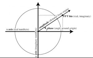
However, there are some very useful reasons to control the phase offset of a wave. For example, by leaving the frequency of cycle~ at 0, and continuously increasing its phase offset, you can change its instantaneous value (just as if it had a positive frequency). The phase offset of a sinusoid is usually referred to in degrees (a full cycle is 360°) or radians (a full cycle is 2π radians). In the cycle~ object, phase is referred to in wave cycles; so an offset of π radians is 1/2 cycle, or 0.5. In other words, as the phase varies from 0 to 2π radians, it varies from 0 to 1 wave cycles. This way of describing the phase is handy since it allows us to use the common signal range from 0 to 1.
So, if we vary the phase offset of a stationary (0 Hz) cycle~ continuously from 0 to 1 over the course of one second, the resulting output is a cosine wave with a frequency of 1 Hz.

The resulting output is a cosine wave with a frequency of 1 Hz
Incidentally, this shows us how the phasor~ object got its name. It is ideally suited for continuously changing the phase of a cycle~ object, because it progresses repeatedly from 0 to 1. If a phasor~ is connected to the phase inlet of a 0 Hz cycle~, the frequency of the phasor~ will determine the rate at which the cycle~ object’s waveform is traversed, thus determining the effective frequency of thecycle~.

The effective frequency of the 0 Hz cycle~ is equal to the rate of the phasor~
The important point demonstrated by the tutorial patch, however, is that the phase inlet can be used to read through the 512 samples of cycle~ object’s waveform at any desired rate. (In fact, the contents of cycle~ can be scanned at will with any value in the range 0 to 1.) In this case, line~ is used to change the phase of cycle~ from .75 to 1.75 over the course of 10 seconds.

The result is one cycle of a sine wave. The sine wave is multiplied by a ‘depth’ factor to scale its amplitude up to 8. This sub-audio sine wave, varying slowly from 0 up to 8, down to -8 and back to 0, is added to the frequency of Oscillator B. This causes the frequency of Oscillator B to fluctuate very slowly between 1008 Hz and 992 Hz.
• Click on the message box in the lower-left part of the window, and notice how the beat frequency varies sinusoidally over the course of 10 seconds, from 0 Hz up to 8 Hz (as the frequency of Oscillator B approaches 1008 Hz), back to 0 Hz, back up to 8 Hz (as the frequency of Oscillator B approaches 992 Hz), and back to 0 Hz.
