simply noise
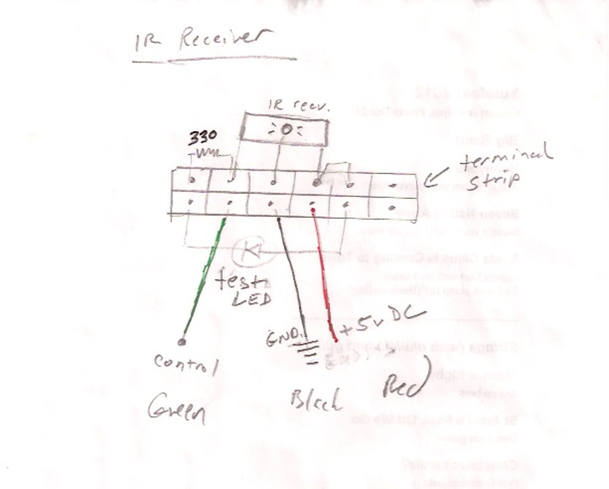
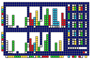
LED interface for rx-320 receiver
implementation of low resolution LED interface for TenTec rx-320 receiver.
Based on this design: https://reactivemusic.net/?p=12408
download
(note: this work is in progress. The github version has not been tested)
https://github.com/tkzic/rx-320
folder: max/LED-project/
files
- ab-rx320-g02.maxpat (main patch)
- colorpanel.pat
- palette.txt
- mod_engine_d.pat
- mod_fb_router.pat
- panel2.js
- rxpanel2.mxb
- rxsynth.xml
hardware
- Behringer BCR-2000 Midi controller
- 2 TenTec rx-320 receivers
- 2 USB to serial adapters
instructions
(in progress)
Connect all the hardware and open ab-rx320-g02 in Max.
Set the MIDI and serial ports as directed in the patch.
notes
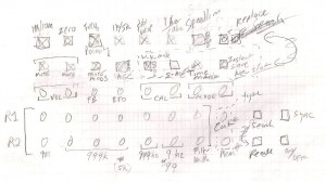
The system uses two TenTec rx-320 radios, controlled by Max. Here is some of the data that is displayed.
- frequency in Hz.
- gain
- filter setting
- mode (AM/SSB)
- Passband shift
- BFO
- frequency calibration
- AGC
- Mute
- scan-mode
- memory presets
- data rate (speed limit)
- time clock
- memory preset selection
- 5 modulator units
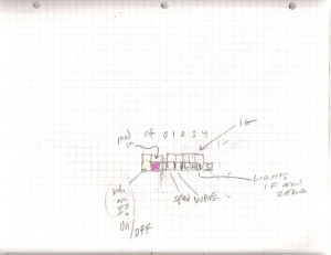
- indicators that show which radio parameters are getting modulated
- and others…
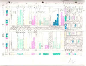
layout
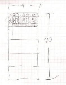
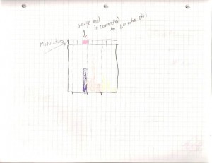
Modulator unit detail
control interface
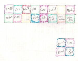
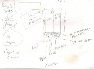
A Behringer BCR2000 provides User input to the radio. Here is a rough layout of the controls:
Button detail
Note there have been changes: Auto cal is now s-match
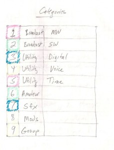
memory preset categories
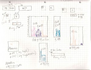
blobs (display units)
modulator destinations (it doesn’t seem to be working like this…)
memory presets – search results:
what’s next
- Need to clean up the control interface – build a template for bcd-2000
- better documentation of LED interface
- write instructions
- more testing
local files
tkzic/max new radio project
main patch: ab-rx320-g02.maxpat
Creative Code Research
VCR’s are analog TV transmitters
Any VCR with antenna output has a built-in RF modulator.
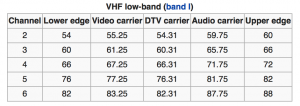
Generally they transmit on channels 2-4. Here are the US frequencies:
from wikipedia http://en.wikipedia.org/wiki/Television_channel_frequencies
The signal is weak, not intended for broadcast. Not legal to broadcast… but hypothetically, amplifiers and antennas could be connected.
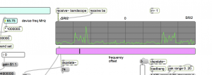
This audio signal is from an iPod playing through a VCR received by rtl-sdr in Max on 65.75 MHz. (channel 3) using a random length wire connected to the antenna output.
Notes about RF modulators:
I have tried this with some small RF modulator boxes. One of the problems is that you need to send a signal to the video input, or the modulator won’t run. You can get a rough signal by patching one of the audio channels into the video input jack. Or a better signal by using the video composite output of a raspberry-pi. Although the VCR gives a much cleaner signal
High Voltage and X-Ray Experiments
By Henning Umland
http://www.celnav.de/hv/hvindex.htm
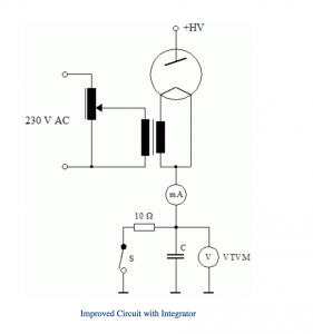
“If, for example, the capacitance of C were 1000 μF, a charge of 1 mAs would result in a voltage of 1 V, independent of any current fluctuations (the capacitor voltage varies in proportion with the charge). I use two paper/oil capacitors with a total capacity of approx. 1500 μF. Thus, a capacitor voltage of 1 V is equivalent to a charge of 1.5 mAs. The time constant resulting from C and the internal resistance of the vacuum tube volt meter, VTVM (Ri = 11 MΩ), is 16500 seconds. Therefore, the capacitor voltage remains virtually constant for some time after the anode current stops flowing. Electrolytic capacitors are not suitable for such a circuit because of their relatively high and unpredictable leak current…”
From “Building a Simple X-Ray Machine”
cloud
What is going on at IBM?
note: 6/2021 – They removed the link to this graphic. I wonder why?
http://www.ibm.com/smarterplanet/us/en/madewithibm/stories/
Europe attacks?
William J. Turkel
Programmer, teacher, historian, and author of “Spark From The Deep”
library of Max patches
At Github: https://github.com/williamjturkel/Max6
The sound of the Internet
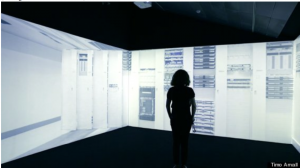
“Internet Machine” by Timo Arnall
by Tyler McCarthy at huffingtonpost.com
