How to add a random post button in WordPress

by teachyourselfwebsites.com

I used this method to add a “random post” to this site. I didn’t create a child theme. So it will break when the theme gets updated.

http://teachyourselfwebsites.com/create-random-post-button-wordpress-blog/

4/24/2016 note:

Here are some details. You need to create a new file inside the theme called page-random.php based on the original page.php.

the added code looks like this and goes right before get_header():


<?php
/* Template Name: Random Post */

$randomPost = get_posts(array(
 'numberposts' => 1,
 'orderby' => 'rand'
));
 
foreach ($randomPost as $post) {
 wp_redirect(get_permalink($post->ID));
 exit();
}

writing delays in C (linux)

An alternative way to write a delay.

You can also use select(2) if you want microsecond precision (this works on platform that don’t have usleep(3))

The following code will wait for 1.5 second:

#include <sys/select.h>
#include <sys/time.h>
#include <unistd.h>`

int main() {
    struct timeval t;
    t.tv_sec = 1;
    t.tv_usec = 500000;
    select(0, NULL, NULL, NULL, &t);
}

Raspberry-Pi RTTY beacon and streaming webcam – success

Update: 5/2014

Retrying this experiment using the Arduino circuit described here: https://reactivemusic.net/?p=12161

notes
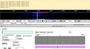
  • 300 baud
  • 300 Hz carrier shift
  • 8 bits
  • 2 stop
  • no parity
  • filter at 300 Hz
  • Normal mode (not reverse)
  • AFC on
There are 2 programs:
  • serial.c – sends a beacon then transmits a 640×480 picture
  • serial-beacon.c – just sends a beacon
In order to view the picture as it comes in in dl-fldigi, you need to open up the SSDV RX window in the View menu.
The frequency is not very stable and occasionally you need to just restart dl-fldigi because the screen fills with trash characters.
Also, in Max, you need to tune on the right half of the picture.
Will be setting up a test with smaller photos


Success: Got an accurate beacon at 300 baud today and send a jpeg picture file , taken by a webcam connected to the R-Pi using fswebcam and SSDV.

http://www.slblabs.com/2012/09/26/rpi-webcam-stream/

Used the same circuit as the previous post about the Arduino RTTY beacon.

The difference is that we’re using a C program to write the text directly to the serial port which modulates the NTX2 transmit frequency.

Transmission can be stopped and started using the sleep() function but the timing is not exact.

Local code

tkzic/rpi/serial/serial1 –

  • using command line SSDV converter in tkzic/rpi/ssdv-master.
  • Using dl-fldigi to decode RTTY and SSDV pictures.
  • Using logictech c210 webcam – see link above for how to take a picture and save to file use fswebcam.


[Todo:]

  • Set up a shell script to take pictures and transmit regular intervals.
  • upload code and photos
  • Build some antennas
  • Field test
  • Buy a balloon


SSDV encoding, decoding, RTTY

I was able to packetize a jpeg file, send it using RTTY encoded audio, and decode using dl-fldigi to reconstruct the picture –  with a 33% error rate.

Details:

Encode jpeg file (note: file should be fairly small with dimensions that are multiples of 16) Using fsphil’s SSDV software:

./ssdv -e -c KA1IS -i 1 24.jpeg test1.pkt

decode:

./ssdv -d  test1.pkt test3.jpeg

RTTY:

Currently using multimode to encode and dl-fldigi to decode. dl-fldigi is the only software that internally supports the SSDV packets.

To get any results, RTTY must be at ascii, 8 bits, no parity, 2 stop bits. The other settings I will need to tweak for maximum throughput, but with this simple setup the error rate was way too high. Especially considering there was no radio involved.

Any way it sort of works


Adafruit Raspberry Pi console cable and drivers

These instructions are better than the Adafruit tutorial. It uses the Mac OS terminal and the driver installation is different in Lion.

http://svbreakaway.info/tp-raspi.php

Combine with these instructions for using Minicom to test the port

http://www.hobbytronics.co.uk/raspberry-pi-serial-port

I was able to use cool-term and mini-com (with local echo set on each one) to have a 2 way terminal session at 9600 baud.

Next – we’ll try to use the serial port to send RTTY using the Arduino method.


Balloon project

notes

Cost estimates rising. I think we’re looking at around $700 possibly more. The balloon, parachute, and helium costs are fixed. Need a source of helium. Might try the sun.

Tracking options:
  • Commercial service like Spot messenger GPS. $100 plus annual service fee of $150
  • Amateur RTTY + GPS – Have built a prototype using arduino. cost will be about $120 – but arduino can be used for many other purposes. Can be tracked by anyone with 70cm receiver. ie., all hams.
  • Amateur APRS – Allows worldwide automatic tracking via APRS network. Cost will run about $250 but provides the most extensive automated tracking network possible. Recommend using Byonics equipment for this.
  • Xbee 900mhz 9600 baud radios (from Sparkfun electronics) These radios provide accurate long range tracking, and interface easily with arduino. Down side is that nobody else can track the flight.
  • Emergency GPS tracker units. Like the ones that skiers use. Haven’t priced these but they would provide a way to find the payload long after it lands.
Sensors:

Recommended sensors would include temperature, pressure, altitude, light levels. These should be fairly inexpensive and can be connected to Arduino

Cameras:

Originally I had wanted to have some kind of live web cam thing, but it appears to require extremely high rate of radio transmission which means live tracking with a mobile unit that has a high gain antenna with programmable azimuth and elevation.

So… logistically, the easiest alternatives then involve the need to recover the payload. These include

  • ordinary camera which is triggered at regular time intervals
  • video camera which runs all the time
  • web cam hooked to a raspberry pi which saves data to SD card
  • web cam/ sd card combo controlled by arduino – more difficult.


RTTY with Arduino

Transmitting on 434.650 MHz.

Successfully ran the configuration described in this article

By Anthony Stirk at UKHAS

http://ukhas.org.uk/guides:linkingarduinotontx2

Have only tried 50 baud – but the beacon ran for over an hour without errors. The receiving   setup was done on a Windows 7 computer:

  • Funcube (software defined radio)
  • FCHID (software to tune the Funcube)
  • Spectraview (demodulate signal from Funcube to SSB)
  • FLDigi (decode RTTY using custom setup)

The bandwidth of the RTTY signal was close to 900 instead of something more reasonable like 50. This can be adjusted by trying various resistor values in the voltage divider circuit.

Next steps include building antennas and increasing the baud rate.


using a WiFi router as a closed local network

I set up a WiFi router today at school, with no internet connection to use for ssh logins to Raspberry Pi and OSC experiments with Arduino. It has the same SSID as my home router so it will be interesting to see what happens when I go from one place to the other. 

Update: Actually this works great. Have been using it for any situation that requires OSC.

FM Midi Synthesizer with Pd on Raspberry Pi

Here’s a simple FM Midi synthesizer developed in pd running on a Raspberry Pi. The patch was written and tested on a Macbook, then the patch file is uploaded to RPi and run using pd-extended from the command line. For example the command to run this patch is:

pd-extended -nogui -noadc -midiindev 1 piSynth1.pd

[todo: upload patch to this site. Currently in tkzic/rpi/pd/piSynth1.pd]

[udpate]: when trying this again, a few problems came up:

  1. R-Pi didn’t recognize sound card/midi: Solution was to connect the sound card directly to the R-Pi USB port and connect the Midi controller via powered USB hub
  2. Sometimes pd-extended errors out with a device busy message. Seems to run ok if you press ctrl-c and repeat the pd-extended command line. I think this problem may be due to a previous process hanging – and not exiting cleanly


pd-extended on Raspberry Pi

notes

Using installation instructions from Pd site:

http://puredata.info/downloads/pd-extended-0-43-3-on-raspberry-pi-raspbian-wheezy-armhf

Installation worked fine. I tried running the GUI under xterm and it was a disaster. Then, using this post, I was able to get a test patch (sine wave with LFO) running in terminal mode:

http://log.liminastudio.com/programming/running-puredata-on-the-raspberry-pi

Note: I changed the actual command to this due to the fact I’m running pd-extended and a USB sound card:

pd-extended -nogui -noadc testPatch.pd

This post from same source has instructions for installing pd-extended (disaster) but a very nice version of the test patch called testPatchExtended.pd

http://log.liminastudio.com/writing/tutorials/how-to-build-pd-extended-on-the-raspberry-pi

(another update) running Midi:

To run midi you need to specify the device on the command line. First I plugged in the m-audio key station 49 and rebooted RPi

To get a list of devices use:

pd-extended -nogui -listdev

Then to run a patch with midi

pd-extended -nogui -noadc -midiindev 1 testMidi.pd

Here is a page with more information on command line options

http://crca.ucsd.edu/~msp/Pd_documentation/x3.htm#s4

(another update) Testing with Griffin iMic. Bad news when doing an ADC->DAC passthrough, sample rates above 32000 don’t work in stereo. However 44100 and 48000 sound fine in mono.

At the higher rates in stereo, the audio breaks up. Oh well. Need to try the Behringer audio box, but I’m assuming there will be no difference. Only possibility would be to somehow devote more system resources to audio.