FM, AM, and SSB modulation/demodulation in Max

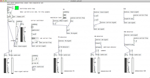
This is a radio – but also a modem, in a literal sense of the word. You may be familiar with AM and FM. Have your tried using them backwards?

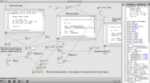
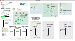
In this patch, an audio signal is modulated using SSB, AM, and FM then frequency shifted to about 1/4 the nyquist frequency. Then the process is reversed revealing the original audio.

notes

Have improved and simplified FM and AM detection. There is no frequency shift prior to detection. This eliminates some phase distortion.

Pd Version. (runs at 44.1 kHz, because I was too lazy to figure out how to do audio file playback which detects the SR of the audio file.

FM detection: The DC offset and makeup gain levels are sensitive to carrier frequency and SR. Will need to automate these corrections to prevent audio output problems.

download

max-projects: https://github.com/tkzic/max-projects

folder: demodulation/max

  • modem3.maxpat
  • obama.aiff

folder: demodulation/pd

  • modem-pd.pd
  • freqshift-abs~.pd
  • obama.aiff


phase cancellation encryption in Max

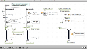
This patch mixes two audio signals, then makes one disappear by reversing its phase. A similar method was used by U.S. military to encrypt radio transmissions during the 20th century. A  phonograph record was the ‘key’ to unlock the encoded transmission. In practice it was difficult to synchronize the two recordings to achieve phase cancellation.

download

https://github.com/tkzic/max-projects

folder: phase-cancellation

patches:

  • phase-cancellation-example.maxpat
  • disappearing-act.maxpat


PID controller in Max

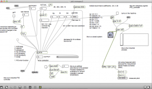
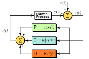
Here is a PID controller (proportional, integral, derivative) in Max that controls the pitch of an oscillator so you can watch how a process responds to various setting of PID coefficients. It features an external perturbance generator (ie., noise maker) to check how fast the system can adjust and continue.

Tried using fiddle~ for frequency detection (as the sensor input) but it provides faulty data below about 200hz – and that totally messes up the PID. so I am just using the actually frequency being used to set the oscillator as the response sensor.

update:  Tristan Jehan wrote a Max external that extends lower frequency range of  [fiddle~]. It would be worth trying for this patch.

The PID algorithm is written in javascript.

download

https://github.com/tkzic/max-projects

folder: pid-controller

patch: pid-mrmapes2.maxpat

javascript code: pid.js

Instructions

  • turn on audio
  • change test interval to something like 20
  • click on message boxes to change set point. Listen and watch results
  • try different presets – which alter PID settings and then try changing the set point. For example, with the 2nd preset you will see overshoot and oscillation during settling phase.

more about PID controllers

wikipedia page: http://en.wikipedia.org/wiki/PID_controller


Phase locked loop FM detection in Max

Here is an example of audio from the patch.

The source is a speech by Barack Obama which is FM modulated on an audio carrier at 23040 Hz.  Warning turn down the volume. You can hear as the PLL locks on to the signal. Then some of the params are tweaked in such a way that it is impossible to lock on to the signal, but the algorithm keeps on trying – producing an interesting result

A picture of the signal as its locking-on and when it loses the lock:

[original post]

A phase-locked loop algorithm running in Max (gen~)

The patch is unstable – but actually demodulates FM now.

download

in max-projects: https://github.com/tkzic/max-projects

folder: demodulation/max/phase-locked-loop

patch

gen-fm-detector2.maxpat

(also uses output from modem3.maxpat in folder: demodulation/max/)

instructions

  • run modem3.maxpat
  • set FM modulation level to less than 250
  • run gen-fm-detector2.maxpat
  • turn up audio output and try presets

notes

Two things: 1) I really don’t know what I’m doing with gen~ and 2) There are serious issues with the P and I coefficients in the algorithm. There is no ‘D’ coefficient yet – nor do I know whether its needed.

The thing that finally got it working was the loop filter component – which cleans up the output of the phase detector. The phase detector is essentially a phase ring modulator which contains not only the error signal, but also the sum of the incoming carrier and the reference oscillator. So the low pass filter gets rid of the high frequency component. By setting the resonance and cutoff extremely low, you can make the PLL start going a bit crazy in a beautiful way, lots of motion and spectral shifting.

Need to go through and analyze the output of the various stages, now to get the coefficients set properly – also, may need some kind of AGC on the input stage. Its very sensitive to over modulation and will distort badly.

Its interesting to play with the coefficients and hear the difference in how the demodulation works. By slowing down the P coefficient  it not only slows lock response, but during lock, the output is muffled  – so the P coefficient acts as a low pass filter – because it changes how responsive the circuit is in detecting changes in the input signal frequency (i.e., modulation).

There’s a weird thing going on – a fixed carrier is getting mixed with the error signal (output)   The patch is using notch filters to eliminate it, but it seems like it shouldn’t be there at all. Or should get filtered by the Loop filter.

Another thing to mention if I haven’t already is that I’m using a somewhat inefficient way to detect phase difference. Its the convert to complex and slope detection method used in the differentiator – but done using signals from reference oscillator instead of from delayed samples from original signal. Simply multiplying the two signals without complex conversion would probably do.

Adam Rokhsar’s Max frame subtraction example

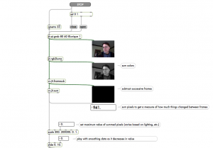
Uses video frame subtraction in jitter to control playback of audio clip.

download

https://github.com/tkzic/max-projects

folder: frame-subtraction

patch: frameSubtraction_example.maxpat

You will also need an audio file: aiff, wav, etc., to load into a Max buffer.

dependencies

You will also need the cv.jit library (computer vision): http://jmpelletier.com/cvjit/

Add the location of these files to your path in Max using Options | File Preferences.

Note: When I loaded the patch in Mac OS 10.8 – the computer automatically downloaded and installed Java updates.

instructions

  • Load an audio file for playback
  • Try setting minimum summed pixels to 150,000 or less for greater effect – depending on amount of light in the room

Arduino with touchOSC and Max

Bi-directional communication from touchOSC to Arduino using an ethernet shield.
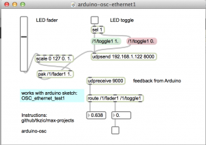
In this version, the Macbook is directly connected to the Arduino to provide a serial monitor for status updates. 

How it works: press a toggle, or move a fader, in touchOSC – it sends a message to the Arduino which lights up, or fades, an LED – then sends back an OSC message to touchOSC to light up the toggle button. (note: local feedback should be off for the toggle button in touchOSC. This is the default)

Arduino circuit
  • Use an ethernet shield. 
  • Connect ethernet cable. (I am using a Netgear WNCE2001 ethernet to wiFi adapter)
  • LED is connected to pin 5 and ground. The shorter lead connects to ground.

download

https://github.com/tkzic/max-projects

folder: arduino-osc

files
  • Arduino sketch: OSC_ethernet_test1/
  • touchOSC screen: simple (default) uses /1/fader1 and /1/toggle1
  • Max patch: arduino-osc-ethernet1.maxpat
Arduino files and libraries

***update 1/20/2016 there is a new sketch that uses the OSCuino library from CNMAT instead of ardosc. The sketches should be interchangeable. https://github.com/CNMAT/OSC . The sketch is in a folder called: OSCuino_tz and is based on work by Trippylightning at: http://trippylighting.com/teensy-arduino-ect/touchosc-and-arduino-oscuino/

Copy the OSC_ethernet_test1/ folder to Documents/Arduino. This puts it in the Arduino sketchbook.

The sketch uses: #include <ArdOSC.h>

Download ArdOSC from: https://github.com/recotana/ArdOSC

  1. After downloading, copy the ArdOSC-master folder to /Documents/Arduino/Libraries
  2. Rename the folder to ArdOSC

This post was the key to figuring out how to make this work: http://arduino.cc/forum/index.php?topic=137549.0

Instructions
  1. Connect Arduino to Macbook via USB.
  2. Open the Arduino serial monitor to initialize the ethernet connection and display the IP address.
touchOSC
  1. In touchOSC or Max, set the target IP to the one just displayed in the Arduino serial monitor
  2. From touchOSC (or Max) send on port 8000, receive on port 9000.
  3. Use the default touchOSC layout (simple)
  4. Use /fader1 and /toggle1 to control the LED
Max
  1. Open arduino-osc-ethernet1.maxpat
  2. Set ip address in [udpsend] to the one just displayed in the Arduino serial monitor
  3. Have some fun
Fixed IP address

update 1/2016: A version of the Arduino sketch that uses a fixed IP instead of DHCP is located in the folder: OSC_ethernet_fixedIP/

The IP is set to 192.168.1.177 but you can change it to any valid address on your network.

Arduino sketch
// generic Arduino OSC program 
// works from Max or touchOSC
//
// plug LED into pin 5 (and gnd)
//
// requires ethernet shield
//
// use serial monitor to get the ip address
//
// use these OSC commands (will work from first page of touchOSC simple layout
//
// /1/fader1
// /1/toggle1
//
#include <SPI.h>
#include <Ethernet.h>
#include <ArdOSC.h>

byte mac[] = { 0x90, 0xA2, 0xDA, 0x0D, 0x0B, 0xCE }; //physical mac address
OSCServer server;
OSCClient client;
int serverPort = 8000; //Touch OSC Port (outgoing)
int destPort = 9000; //Touch OSC Port (incoming)
int ledPin = 5; 
int flag=0;
void setup(){
pinMode(2, OUTPUT);
 Serial.begin(9600); 
 Serial.println("DNS and DHCP-based OSC server");
 // start the Ethernet connection:
 if (Ethernet.begin(mac) == 0) {
 Serial.println("Failed to configure Ethernet using DHCP");
 // no point in carrying on, so do nothing forevermore:
 while(true);
 }
 // print your local IP address:
 Serial.print("Arduino IP address: ");
 for (byte thisByte = 0; thisByte < 4; thisByte++) {
 // print the value of each byte of the IP address:
 Serial.print(Ethernet.localIP()[thisByte], DEC);
 Serial.print("."); 
 }
 Serial.println();
 Serial.println();
//start the OSCserver
 server.begin(serverPort);
//add OSC callback function. One function is needed for every TouchOSC interface element that is to send/receive OSC commands.
 server.addCallback("/1/toggle1", &funcOnOff);
 server.addCallback("/1/fader1", &funcFader);
}
void loop(){
if(server.aviableCheck()>0){
 // Serial.println("alive! ");
 } 
}
//When the button on the TouchOSC inteface is pressed, a message is sent from the iDevice
//to the Arduino to switch (togle) the LED on the Arduino on/off
//then a messeage is sent bak from the Arduino to the iDevice to toggle the buttom on/off
void funcOnOff(OSCMessage *_mes){
 float value = _mes->getArgFloat(0); //TouchOSC expects float values
//create new osc message
 OSCMessage newMes;
//set destination ip address & port no
 newMes.setAddress(_mes->getIpAddress(),destPort);
 newMes.beginMessage("/1/toggle1");
Serial.println(value);
 if(value < 1.0) {
 digitalWrite(ledPin, LOW);
 }
 else{
 digitalWrite(ledPin, HIGH);
 }
newMes.addArgFloat(value);
//send osc message
 //
 // turn local feedback off on touch-osc control to test this
 client.send(&newMes);
}
// new callback for fader - using same comments
//When the button on the TouchOSC inteface is pressed, a message is sent from the iDevice
//to the Arduino to switch (togle) the LED on the Arduino on/off
//then a messeage is sent bak from the Arduino to the iDevice to toggle the buttom on/off
void funcFader(OSCMessage *_mes){
 float value = _mes->getArgFloat(0); //TouchOSC expects float values
//create new osc message
 OSCMessage newMes;
//set destination ip address & port no
 newMes.setAddress(_mes->getIpAddress(),destPort);
 newMes.beginMessage("/1/fader1");
Serial.println(value);
 int ledValue = value * 255.0;
 analogWrite(ledPin, ledValue);
newMes.addArgFloat(value);
//send osc message
 //
 // turn local feedback off on touch-osc control to test this
 client.send(&newMes);

}


Slew limiter in Max

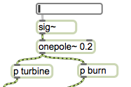
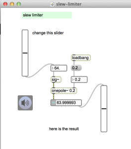
Setting the  cutoff frequency of a lowpass filter to sub audio frequencies creates a portamento effect when used with control signals.

This Max example was adapted from a Pd jet engine patch by Andy Farnell in “Designing Sound”. Its used as an inertial delay, or portamento to ramp up and down the pitch of the engine.

The LPF needs to be extremely low frequency.

download

max-projects: https://github.com/tkzic/max-projects

folder: slew-limiter

  • slew-limiter.maxpat