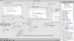
Here is an example of audio from the patch.
The source is a speech by Barack Obama which is FM modulated on an audio carrier at 23040 Hz. Warning turn down the volume. You can hear as the PLL locks on to the signal. Then some of the params are tweaked in such a way that it is impossible to lock on to the signal, but the algorithm keeps on trying – producing an interesting result
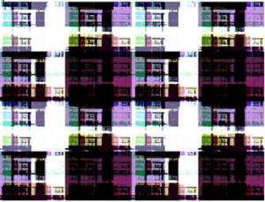
A picture of the signal as its locking-on and when it loses the lock:
[original post]
A phase-locked loop algorithm running in Max (gen~)
The patch is unstable – but actually demodulates FM now.
download
in max-projects: https://github.com/tkzic/max-projects
folder: demodulation/max/phase-locked-loop
patch
gen-fm-detector2.maxpat
(also uses output from modem3.maxpat in folder: demodulation/max/)
instructions
- run modem3.maxpat
- set FM modulation level to less than 250
- run gen-fm-detector2.maxpat
- turn up audio output and try presets
notes
Two things: 1) I really don’t know what I’m doing with gen~ and 2) There are serious issues with the P and I coefficients in the algorithm. There is no ‘D’ coefficient yet – nor do I know whether its needed.
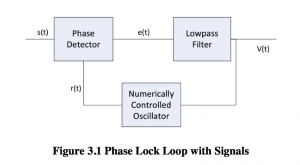
The thing that finally got it working was the loop filter component – which cleans up the output of the phase detector. The phase detector is essentially a phase ring modulator which contains not only the error signal, but also the sum of the incoming carrier and the reference oscillator. So the low pass filter gets rid of the high frequency component. By setting the resonance and cutoff extremely low, you can make the PLL start going a bit crazy in a beautiful way, lots of motion and spectral shifting.
Need to go through and analyze the output of the various stages, now to get the coefficients set properly – also, may need some kind of AGC on the input stage. Its very sensitive to over modulation and will distort badly.
Its interesting to play with the coefficients and hear the difference in how the demodulation works. By slowing down the P coefficient it not only slows lock response, but during lock, the output is muffled – so the P coefficient acts as a low pass filter – because it changes how responsive the circuit is in detecting changes in the input signal frequency (i.e., modulation).
There’s a weird thing going on – a fixed carrier is getting mixed with the error signal (output) The patch is using notch filters to eliminate it, but it seems like it shouldn’t be there at all. Or should get filtered by the Loop filter.
Another thing to mention if I haven’t already is that I’m using a somewhat inefficient way to detect phase difference. Its the convert to complex and slope detection method used in the differentiator – but done using signals from reference oscillator instead of from delayed samples from original signal. Simply multiplying the two signals without complex conversion would probably do.


