Low resolution LED interface

Lots of information in a few pixels.

Computer displays have evolved to high resolutions. What about the other direction? This experiment  is a display interface using a grid of LED’s. Essentially, very large pixels.

information types
  • on/off 
  • small numbers (0-10)
  • large numbers (0-10,000,000)
  • clocks
  • level indicators
  • connections
  • map keys (i.e., explanations of symbols) 
communicating with LED’s

LED’s communicate information using

  • brightness
  • color
  • movement
ideas

With just a few LED’s its easy to display a clear message. A large matrix of LEDS can get confusing. Here are a few suggestions:

  • Use separate regions for each block of information.
  • Draw guide markers to help locate positions by giving frame of reference.
  • Animation catches the eye but also distracts, and confuses.

examples

traffic lights

An effective but inefficient signaling method.

resistor codes:

Resistors use a numeric color code.

Find the value of any resistor by looking at the first four 4 color bands. Colors represent  base 10 exponential notation.

abacus

An abacus uses 5 or 10 beads for each digit. Faster than decoding a resistor and works with one color – but takes up more space.

level meters

Segmented level meters convey information using a line of pixels:

binary clock

Represents digits using binary coded decimal notation.

An LED grid in Max

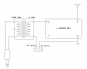
This grid design was used for the visual interface of a shortwave radio:

And an etch-a-sketch:

download

https://github.com/tkzic/max-projects

folder: LED-display/rx-320/

files:

  • rxpanel2.maxpat (main patch)
  • panel2.js (javascript)

instructions

There are 2 large toggles – one for etch-a-sketch, and another for the radio simulator. Try one, then toggle it off before trying another one. If you forget – just restart the patch.

The number box near the top can be used to expand or contract the display size (while it is active) The default size is 17.

how it works

The same patch generated both video examples above. It uses javascript to make a two dimensional array of Max led objects. Each object is addressable by its position in the array. Here’s the code to make the objects:

//
// makecells - create matrix of led objects
//
function makecells( x, y, color )
{

var p;		// this patcher
var tmpstr;
var objname;

	post( "makecells: ", x, y, color );
	post( );

	p = this.patcher;

// make cells

	for( i = 0; i < x; i++ )
		{
		for(j = 0; j < y; j++ )
			{
			cell[i][j] = p.newdefault(xorigin + (i * cellspace), yorigin + (j * cellspace), "led" );    // create leds
			if(color != 9 )
				{
				cell[i][j].hidden = 0;
				cell[i][j].message( "pict", color );
				}
			else
				{
				cell[i][j].hidden = 1;
				}

			cell[i][j].varname = "led" + i + "x" +  j;							//  assigns name for future use	
			}
		}

}


blobs

Although each LED in a grid is addressable, its easier to group sections of the grid into blobs. Each blob is a unit that displays data, like a number for example. There are several types of blobs:

Here are the properties of a blob:

//  blob data structure
//
//   x, y upper left
//   lengthx, lengthy, 
//
//   orientation: 0 = horizontal, 1 = vertical
//   step  1 = downward or rightward,  -1 = upward or leftward  (this defines the corner of origin too)
//
//   data lorange, hirange
//   scale: 0 = no, 1 = yes
//
//   blobtype: 0 = generic decimal,  1 = spare,  2 = pushbutton flash,  3 = radiobutton, 
//   color code 0-9
//   contrast color 0-9
//
//   signed ( 0 = no, 1 = yes)		// booooooooooooooolean  
//   colorshift ( 0 = normal , 1 = use different colors every 3 digits, like comma separators (frequency display)
//
//   blink  (milliseconds duration for pushbutton flash type only (led blinktime )
//      
//   radio number
//   name
//   value
//
//


Blob data examples

Lets look at examples of various ways to display data – as used in the shortwave radio video above.

Here are 3 blobs that represent numbers in three different ways.

The far left column and the bottom row are key graphics. They give a frame of reference for the data.

columns

Moving from left to right…

The LED’s far left column, are a graphic key, starting with red on the bottom, represent the numbers 1-9

The next blue column is just a divider

The 3rd column of white dots is the signal strength data ranging from the 0-9. The current value is ‘4’, represented by a column of 4 dots.

The next nine columns (4-12) represent the frequency in Hz. ranging from 0-999,999,999. The data is in groups of three (as you can see by looking at the graphical key in the bottom row). The number currently displayed is: 4,999,991.

Negative frequencies are displayed by shifting the colors to values that don’t match the key graphic.

The last column is a radio button with 4 possible values and is currently set to ‘3’

rows

The bottom row is a key graphic, showing a different color, or group of colors for each data item. So for example, there is one white dot under the signal strength data in column 3. There are 3 groups of 3 dots (yellow, green, yellow) in columns 4-12 representing the frequency data in the format: 999,999,999.

The 2nd blue row from the bottom is a divider.

The next shows which data items are being controlled by modulators. The 3 white LED’s show modulation of frequency data in the million’s, 100’s, and ten’s  places.

Modulator units

There are 5 modulator units in the display. Data is represented using a color code..

  1.  red
  2. green
  3. blue
  4. yellow
  5. white

Gray LED’s represent ‘momentary’ controls in the off state. When a momentary button is pressed, it will blink white.

Here is an example of a modulator unit

The blue LED’s are just dividers (background space)

columns

The first column of data on the left is the on/off indicator and the modulator’s ID number.

The top LED of the column is the on/off toggle. It is blank, which means off.

The next two red LED’s together represent the ID number of the modulator: red = 1

For the remaining columns, the top row indicates whether the input gate is open allowing other modulators to control the parameter. Grey indicates the gate is closed, A white LED means the input gate is open.

The second and third columns of data are the clock speed and wave type. The 2 LEDS in each column are grouped together and are using the color code above. The clock speed is 5 (white). The wave type is 4 (yellow)

The fourth and fifth columns of data are the low and high range. Low range value is 5 (white) and high range value is 2 (green) – which doesn’t make sense, but this is simulator data.

The last column is the modulator destination activity indicator: grey if zero (not assigned) or white if any non-zero value.

modulator data structure:
// modulator data structure
// these are fixed structures 8x2, with specific color rules
//
// ulx, uly
// mod id number 1-n 
// on	: 0 = off, 1 = on
// modin :  modulation source index 0-4
// clockspeed  :  0-4
// wavetype : 0-4
// lorange : 0-4
// hirange : 0-4
// ingate : 0 - 4  (tells which control is being modulated)
// spare
// destination : 0-127 destination index  // this is displayed elsewhere
//


hardware interface

Adafruit 32×32 RGB LED panel

https://www.adafruit.com/products/1484?gclid=CMzrnYDB1b4CFTQQ7AodjXkAFw

local file notes:

files are also in tkzic/new max radio project/

There is a newer version adapted for the Max radio project – basically same code, but file names are

  • rxpanel3.maxpat
  • panel3.js


rx-320 control

Operate the TenTec rx-320 receiver in Max.

A simple control program. Features save/recall memory presets with random scanning.

download

https://github.com/tkzic/rx-320

folder: max/receiver

instructions

  • Click the print message near the serial object to get a list of the serial ports in the Max window
  • Unlock the patch and edit the serial object to use the correct port letter

notes

  • runs in Mac OS and Windows
  • It would be worth checking the code that sets frequency and BFO against the newer code in the LED-project. I can’t remember if I updated this older version
  • There is also a version of this program that runs with ICOM ic-746 receiver

VCR’s are analog TV transmitters

Any VCR with antenna output has a built-in RF modulator.

Generally they transmit on channels 2-4. Here are the US frequencies:

from wikipedia http://en.wikipedia.org/wiki/Television_channel_frequencies

The signal is weak, not intended for broadcast. Not legal to broadcast… but hypothetically, amplifiers and antennas could be connected.

This audio signal is from an iPod playing through a VCR received by rtl-sdr in Max on 65.75 MHz. (channel 3) using a random length wire connected to the antenna output.


Notes about RF modulators:

I have tried this with some small RF modulator boxes. One of the problems is that you need to send a signal to the video input, or the modulator won’t run. You can get a rough signal by patching one of the audio channels into the video input jack. Or a better signal by using the video composite output of a raspberry-pi. Although the VCR gives a much cleaner signal

AM audio transmitter using Arduino

Transmit AM audio on 727 KHz. using a voltage divider and an Arduino.

By Markus Gritsch

Note: with the actual circuit the signal is closer to 760 KHz.

Samples incoming audio at 34 KHz. and rebroadcasts as RF using the Arduino clock.

This is a simplification of Markus’ original circuit. It eliminates the tuned output circuit. Probably at the expense of increased harmonic distortion.

The voltage divider is uses 2 47K Ohm resistors and a 1 uF electrolytic capacitor. It is the input half of the original circuit.

http://dangerousprototypes.com/forum/viewtopic.php?f=56&t=2892#p28410

(I substituted 2 100 K Ohm resistors in parallel for each of the 47 K’s.)

A voltage divider is useful as a general purpose coupler, for sampling analog signals using  Arduino PWM input.

The Arduino sketch is Markus’ original – reprinted here:

(note) Local file is AM_audio_transmitter.

// Simple AM Radio Signal Generator :: Markus Gritsch
// http://www.youtube.com/watch?v=y1EKyQrFJ−o
//
// /|\ +5V ANT
// | \ | /
// | −−−−−−−−−−−−−−−− \|/
// | | R1 | Arduino 16 MHz | C2 |
// | | 47k | | || | about
// audio C1 | | | TIMER_PIN >−−−−−||−−−−−+ 40Vpp
 // input || | | | || |
 // o−−−−−||−−−−−+−−−−−−−> INPUT_PIN | 1nF |
 // +|| | | | )
 // 1uF | | R2 | ATmega328P | ) L1
 // | | 47k −−−−−−−−−−−−−−−− fres = ) 47uH
 // fg < 7 Hz | | 734 kHz )
 // | |
 // | |
 // −−− GND −−− GND
 //
 // fg = 1 / ( 2 * pi * ( R1 || R2 ) * C1 ) < 7 Hz
 // fres = 1 / ( 2 * pi * sqrt( L1 * C2 ) ) = 734 kHz

#define INPUT_PIN 0 // ADC input pin
#define TIMER_PIN 3 // PWM output pin, OC2B (PD3)
#define DEBUG_PIN 2 // to measure the sampling frequency
#define LED_PIN 13 // displays input overdrive

#define SHIFT_BY 3 // 2 ... 7 input attenuator
#define TIMER_TOP 20 // determines the carrier frequency
#define A_MAX TIMER_TOP / 4

void setup() {
pinMode( DEBUG_PIN, OUTPUT );
pinMode( TIMER_PIN, OUTPUT );
pinMode( LED_PIN, OUTPUT );

// set ADC prescaler to 16 to decrease conversion time (0b100)
ADCSRA = ( ADCSRA | _BV( ADPS2 ) ) & ~( _BV( ADPS1 ) | _BV( ADPS0 ) );

// non−inverting; fast PWM with TOP; no prescaling
TCCR2A = 0b10100011; // COM2A1 COM2A0 COM2B1 COM2B0 − − WGM21 WGM20
TCCR2B = 0b00001001; // FOC2A FOC2B − − WGM22 CS22 CS21 CS20

// 16E6 / ( OCR2A + 1 ) = 762 kHz @ TIMER_TOP = 20
OCR2A = TIMER_TOP; // = 727 kHz @ TIMER_TOP = 21
OCR2B = TIMER_TOP / 2; // maximum carrier amplitude at 50% duty cycle
}

void loop() {
// about 34 kHz sampling frequency
digitalWrite( DEBUG_PIN, HIGH );
int8_t value = (analogRead( INPUT_PIN ) >> SHIFT_BY ) - (1 << (9 - SHIFT_BY ));

digitalWrite( DEBUG_PIN, LOW );

// clipping

if( value < -A_MAX) {

  value = -A_MAX;
  digitalWrite( LED_PIN, HIGH );
  } else if ( value > A_MAX ) {
  value = A_MAX;
  digitalWrite( LED_PIN, HIGH );
  } else {
  digitalWrite( LED_PIN, LOW );
  }

OCR2B = A_MAX + value;

}


FM audio transmitter using NTX2

Transmit FM audio on 434.65 Mhz. by substituting a Radiometrix NTX2  for a crystal oscillator in this circuit:

http://scitoys.com/scitoys/scitoys/radio/am_transmitter.html

Radiometrix: http://www.radiometrix.com/content/ntx2

NTX2 datasheet: http://www.radiometrix.com/files/additional/ntx2nrx2.pdf

On the NTX2, the connections are:

  • 5V to the NTX2 VCC pin 4
  • 5V to the NTX2 EN pin 5
  • GND to the NTX2 GND pin 6
  • Upper lead of audio transformer to the NTX2 TXD pin 7

A voltage divider input coupler will also work. See this post for a simple circuit: https://reactivemusic.net/?p=12263

notes

  • Audio modulation level is very low. This circuit would benefit from a preamp. For example, as in this circuit by Amanda Ghassaei: http://www.instructables.com/id/Arduino-Audio-Input/
  • Connect an antenna wire to NTX2 pin 2 (and 1 for RF ground)
  • The circuit worked with 3.3 volts and would probably be fine with less.
  • Used line out of an iPod touch for an audio source. Volume was up fairly high.
  • You can also receive using AM mode using ‘edge’ detection
  • In the US, you need a ham license to transmit on 434.65 Mhz.

RTTY with Arduino and NTX2

A circuit from the UK High Altitude Balloon sight, that sends RTTY, from Arduino using the Radiometrix NTX2 transmitter on 434.650 Mhz.

http://ukhas.org.uk/guides:linkingarduinotontx2#where_to_buy_the_ntx2

circuit notes

substituted  2 100k resistors in parallel for the 47k connected to TX output in the circuit

RTTY settings

We used rtl-sdr with Max as the receiver, in SSB mode, sending audio via Soundcloud to dl-fldigi to decode the RTTY. The params that worked:

  • 50 baud
  • carrier shift 400-480 hz (varies)
  • 7 bits per char
  • no parity
  • 2 stop bits
  • reverse mode on
audio input monitor in dl-fldigi

Unfortunately there was no way to hear the signal while decoding because dl-fldigi doesn’t feed through the input audio. A workaround is to run  Audacity in the background. In audacity:

  • set input to soundflower,
  • set output to built-in output
  •  press pause
  •  press record – now you should hear the radio.

pwm circuit

An updated version of the system described above.

This circuit features no additional components. Just the NTX2 and Arduino. The voltages are generated using PWM (pulse width modulation).

Described in a 3 part series.

by Anthony Stirk at ava.upuaut.net

http://ava.upuaut.net/?p=617

Example 1 – testing

The first example generates a carrier shift of 310 Hz. It took several minutes for the transmit frequency to stop drifting. The AFC setting in dl-fldigi helps to keep things locked in – as long as their is a constant carrier.

Example 2 – RTTY

Reducing the filter bandwidth to less than 150 Hz helps, due to the narrow carrier shift.

Example 3 – dominoEX MFSK

Requires a 175 ohm resistor for precise timing. Didn’t have one, so I just ran the sketch without decoding. Here’s what it sounds like:

what’s next?
  • decoding RTTY in Max