A Searchable Google map.

update 6/2014: latest version of MaxSDR offers FCD pro+ drivers: http://zerokidz.com/radio
original post
A fork of the David Pella code which was the basis for the MaxSDR project externals. It seems plausible that we could modify the drivers and get MaxSDR working with the funCube pro+.
By Alex Csete, OZ9AEC
http://www.oz9aec.net/index.php/funcube-dongle/479-the-funcube-dongle-propro-on-the-raspberry-pi
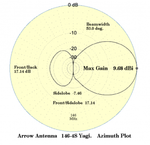
Tracking high altitude balloon telemetry on 434 Mhz.
By Arrow antennas
http://www.arrowantennas.com/index.html
Also by Cushcraft:
http://www.gigaparts.com/store.php?action=profile&sku=ZCC-A43011S
Update: 5/2014
Retrying this experiment using the Arduino circuit described here: https://reactivemusic.net/?p=12161

Success: Got an accurate beacon at 300 baud today and send a jpeg picture file , taken by a webcam connected to the R-Pi using fswebcam and SSDV.
http://www.slblabs.com/2012/09/26/rpi-webcam-stream/
Used the same circuit as the previous post about the Arduino RTTY beacon.
The difference is that we’re using a C program to write the text directly to the serial port which modulates the NTX2 transmit frequency.
Transmission can be stopped and started using the sleep() function but the timing is not exact.
tkzic/rpi/serial/serial1 –
[Todo:]
A variety of projects: like interrupt driven RTTY code for Arduino.
By Anthony Stirk

Another SSDV flight project from Philip Heron:
https://github.com/ProjectSwift/swift
I was able to packetize a jpeg file, send it using RTTY encoded audio, and decode using dl-fldigi to reconstruct the picture – with a 33% error rate.
Details:
Encode jpeg file (note: file should be fairly small with dimensions that are multiples of 16) Using fsphil’s SSDV software:
./ssdv -e -c KA1IS -i 1 24.jpeg test1.pkt
decode:
./ssdv -d test1.pkt test3.jpeg
RTTY:
Currently using multimode to encode and dl-fldigi to decode. dl-fldigi is the only software that internally supports the SSDV packets.
To get any results, RTTY must be at ascii, 8 bits, no parity, 2 stop bits. The other settings I will need to tweak for maximum throughput, but with this simple setup the error rate was way too high. Especially considering there was no radio involved.
Any way it sort of works
Here’s Dave Akerman’s explanation of how to write the code to get the Raspberry-Pi to send images via SSDV. It seems kind of impossible…
The usual technique with the NTX2 is to send the ’1′ and ’0′ values in RTTY by waggling a general purpose I/O pin up and down at the correct rate. e.g. every 20ms for the common 50 baud data rate. This is easy when you’re programming a bare-metal AVR or PIC – just use a delay routine or, as in my trackers, a timer interrupt. However the Pi runs a non-real-time operating system, so I could not rely on accurate timing especially if the operating system is busy taking a photo from the webcam. There are other options but I opted for the simplest one – connect the NTX2 to the serial port. RTTY is just normal RS232-style serial marks and spaces and stop bits etc., so why not let the hardware UART do the timing for me? It didn’t take long to write a small ‘C’ program that opened the serial port at 4800 baud, read enough GPS strings to find the longitude, latitude and altitude, then close the port and re-open at 300 baud (I found that switching baud rates without closing and opening wasn’t always reliable) to send out a formatted telemetry string. Of course to do this I had to disable the login prompt on the serial port, and stop the kernel debug messages being sent to it, but all in all it was simple. All of this was done using the standard Debian image on a 4GB SD card.
Now for the live images. I had to apply a patch to Debian after which it happily recognised the webcam as /dev/video0. I tried a few webcams and settled on the Logitech C270 which is reasonable quality, light and cheap (in case the payload goes missing!). I tried several webcam imaging programs and found fswebcam to be the best (worked without fiddling, yet had enough options to tailor the picture taking). Remember that the radio system has low bandwidth and with a typical flight lasting 2 hours or so we don’t have time to send large images, so there’s no point using the very best webcam and the highest resolution. I settled on 432 x 240 pixels with 50% compression as a good compromise between quality and download speed. I measured the webcam current and it went from 50mA at idle to 250mA peak when taking a picture, hence the need to short out the USB fuse (140mA max). A simple shell script took a photo every 30 seconds, saving them on the SD card so that the tracker program could choose the “best” image (largest jpeg!) for transmission. Each chosen image is then converted to the form for download (split into blocks each with FEC) before being sent 1 block at a time. I interspersed the image data with telemetry – 4 image packets for each telemetry packet). Here’s the Pi making a self-portrait:

Also this is very useful
Did you connect the Raspberry PI’s TXD output directly to the Radiometrix TXD line? Or did you use some kind of v3.3 to v5.0 level conversion hardware? If you did level conversion, can you share your design? I am planning to build an APRS transmitter using a cheap USB GPS and a Radiometrix HX1, and I am wondering how complex the connection between the Raspberry Pi and the HX1 needs to be.
Notes on high altitude balloon tracking using APRS.
Byonics TT3 is another option – a separate APRS encoder, to be combined with GPS and transmitter, for example:
What are all the pieces I will need to make a complete TinyTrak APRS tracker?
Transmitting on 434.650 MHz.
Successfully ran the configuration described in this article
By Anthony Stirk at UKHAS
http://ukhas.org.uk/guides:linkingarduinotontx2
Have only tried 50 baud – but the beacon ran for over an hour without errors. The receiving setup was done on a Windows 7 computer:
The bandwidth of the RTTY signal was close to 900 instead of something more reasonable like 50. This can be adjusted by trying various resistor values in the voltage divider circuit.
Next steps include building antennas and increasing the baud rate.

Connected via some resistors to set the level and bias. This means that the low/high digital outputs from the Pi result in 2 slightly different voltages at the NTX2, which then transmits two frequencies approx 600Hz apart.
This won’t work for APRS. For that you need an analog output, or PWM.