By Andrew Mohawk
http://andrewmohawk.com/2012/09/06/hacking-fixed-key-remotes/

Digital Signal Processing – rtlSDR – fall 2012
http://inst.eecs.berkeley.edu/~ee123/fa12/rtl_sdr.html

C++ code available at Safari Books Online.
(Including PLL examples)
By: C. Britton Rorabaugh

http://my.safaribooksonline.com/book/electrical-engineering/communications-engineering/9780132442121
local code is in tkzic/simulating wireless dsp c++
A nice explanation – with Python simulation.
By P. Lutus at arachnoid.com
http://arachnoid.com/phase_locked_loop/

Here is a PID controller (proportional, integral, derivative) in Max that controls the pitch of an oscillator so you can watch how a process responds to various setting of PID coefficients. It features an external perturbance generator (ie., noise maker) to check how fast the system can adjust and continue.

Tried using fiddle~ for frequency detection (as the sensor input) but it provides faulty data below about 200hz – and that totally messes up the PID. so I am just using the actually frequency being used to set the oscillator as the response sensor.
update: Tristan Jehan wrote a Max external that extends lower frequency range of [fiddle~]. It would be worth trying for this patch.
The PID algorithm is written in javascript.
https://github.com/tkzic/max-projects
folder: pid-controller
patch: pid-mrmapes2.maxpat
javascript code: pid.js

wikipedia page: http://en.wikipedia.org/wiki/PID_controller
DSP tools for FM demodulation.
By Ali Naveed, et al.
Software Defined Radio is an emerging technology that has been an active re-search topic for over a decade. The terms software defined radio and software radio are used to describe radios whose implementation is largely software-based. These radios are reconfigurable through software updates. There are also wider definitions of the concept. A software defined uses digital signal processing (DSP) for coding, decoding, modulating, and demodulating data.
The proper implementation of SDR is far away from our approach and the experience which we have gained during the three years studies in the B.E program of Industrial Electronics. That is why, this project is the design, construction, and testing of an FM receiver. The design is split into two portions, the analog FM front end and the digital demodulator. The job of the front end is to receive and down convert the RF signal to a frequency that is low enough to be processed by a DSP processor.
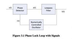
The second portion of the design is the demodulator. The phase lock loop method of demodulating FM signals is used. The phase lock loop demodulator is designed in the digital domain on a DSP processor.
Web audio API extension.
by Hongchan Choi
Dev branch: https://github.com/hoch/WAAX/tree/dev
Hongchan Choi: https://ccrma.stanford.edu/~hongchan/